What follows is “my” (modified) version of the [now defunct] Souther SLA installation instructions – I find it useful to rewrite instructions in my own language and word usage. Disregard if needed. I use gvim with ReST and python3 (sphinx).
INTRODUCTION & CAUTIONS
Congratulations!
You have just purchased one of the finest tonearms available in the entire world of High-End audio components. Your Souther has the capability to extract unprecedented performance from absolutely any phono cartridge. However, to extract this potential from the arm (and your cartridge), you need to take the time to familiarize yourself with both the nomenclature and functions of the Souther SLA arm, and follow these setup instructions very closely and sequentially. It is **imperative** that you follow the sequence of the instructions as written to obtain the best results.
Warning:
Setup is complex, therefore it is critical that you read (completely) the following instructions before you start any adjustments.
PRECAUTIONARY NOTES
* Keep your Souther Linear Arm (SLA) away from direct sunlight, and do not expose it to extreme temperature and/or high-moisture environments; This is true for all electronic equipment.
* Extreme care must be used in handling the cartridge Litz wire so that it does not become kinked or develop any sharp bends or knots. This multi-stranded copper wire is covered with a nylon overlay, so it is both very flexible and stronger than one would expect. The Litz wire is strain-relieved with a black silicone rubber, and has (thus far, with more that 2k arms sold) proven reliable when given normal handling and care.
* Never, repeat, **never** oil or try to clean the three carriage bearings. They are designed to be operated without lubrication and maintained in a dry condition; Using oil or penetrants will simply attract dust to the quartz rails and impinge functionality.
* If the quartz track accumulates too much dust, it may cause skipping or groove repetition, and must be cleaned. If the tracks are dusty of dirty, then use a “Q-tip” that is lightly moistened with rubbing alcohol (or a similar cleaner), and clean the entire track. Use gentle strokes and avoid the glue seam, but clean and dry the rails thoroughly!
* The tonearm dust-cover should be left on the arm during normal operation. Replace after making any adjustments.
* Your warranty will be voided if any screws on the carriage, or the track hold-down screws, are moved or or readjusted! These are not meant to be “reset.” They are to be adjusted at the factory only. Tracks may be adjusted by qualified dealers (only). To date, no DIY modifications to the Souther SLA actually lead to improvements in sound – only reductions in functionality.
UNPACKING
Note:
Save all packing material for possible re-shipment and/or sales.
Your arm is shipped enclosed in a sealed plastic Ziploc bag to keep it clean, along with the remainder of the parts found in the accompanying packaging. You will also find a packing list and your limited warranty. Your arm tubes will be packaged separately in their own container. The Souther linear gauge serves a dual purpose: During shipment it is secured to the chassis with the via screw (the plastic foam under it prevents the carriage from moving.) remove the VTA screw (releasing the gauge) and then, rethread the screw back one half of the way into the same hole. Now, remove the cover by unscrewing the two ‘dust’ cover screws. The dust cover will remain off throughout the following adjustment procedures.
INSTALLATION OF THE CHASSIS
If the turntable has a dedicated arm-board, especially an arm-board that is connected to the platter suspension with springs; e.g., Linn, Sota, Thorens, VPI, etc., then you **must (of course)** locate the SLA hinged base **there**. Otherwise, the chassis placement is non- critical, as we just need a straight shot at the spindle via a radial line, of which we have 360 to choose. Aesthetically, the chassis is best placed parallel to the front of edge the turntable. Some turntables have special mounting arrangement and/or hardware. Refer to the specific turntable listing at the end of this document for further information.
Insert the tubes of the hinged base assembly into the main (Quartz carriage) chassis with the VTA printing facing outward. At this point, check the side play adjustment screw to be sure that there is no side motion between the two sections, i.e., the hinged block with the two vertical stainless tubes and the VTA base molding.
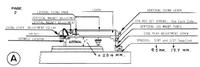
Adjust the VTA screw and the base assembly (tightening the two VTA lock screws) and adjust the spindle locator so that when the chassis is placed on the turntable the chassis is approximately parallel to the top of the platter, and the structural chassis tubes are approximately one inch or twenty five mm (2.54 cm) from the platter. Measure the one inch between the bottom of the structural SLA chassis tubes spacers and the platter surface. See Figures A and B.
Tip:
Lou Souther would use “measured linear offsets” from fixed positions of the arm body to determine positioning - A helpful positioning tactic is to use heavy construction paper (or cardboard) to craft an accurate set of 1” [2.54 cm] high rectangles to slide under the structural arm tubes to verify vertical clearance positioning.
FIG "A"
Decide if you need to use one or more of the spacers provided (1/4” or 1/2”) to span the vertical clearance height needed (approximately 1 inch, or 2.54 cm) . Also note that approximately 5/8” of the vertical leg mount tubes should extend downward below the main end molding when mounted, as this provides for the most **rigid** SLA arm mounting. With a very shallow platter, no spacers will likely be required. On extremely thick or high platters, possibly both spacers will be required, and/or a “platform” to get to the needed height differential.
FIG "B"
Carefully position the hinged base so that the spindle locator is directly on (and fully seated over) the spindle, and maneuver the hinged base to the exact position where you wish to bolt it.
Note:
Whenever the spindle is moved or changed up or down, it must be locked into position holding the knurled nut portion of the locator firmly so that it (the tonearm assembly) does not move and lose the horizontal alignment.
While holding the spindle locator, the “jam nut” (which locks spindle locator into place) must be tightened counter clock-wise (upward) securing it against the spindle locator molding. While in this position, mark the two mounting hole positions, with a suitable scribe or a pencil (a pencil, depending on the arm-board material, works well here!) and make a clear mark on the arm-board.
Note:
It is advisable to extend the dots (marked by the scribe or pencil) into an “X” to allow for a clear drill center ‘target’.
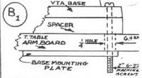
Now remove the arm base, and drill out (vertically) two holes at the marked spots; go completely through the arm-board. These two holes should be slightly oversized for the bolts provided, as in drill out a 1/4 inch (6.35 mm) diameter hole. Remove the VTA hinged base from the chassis and insert the two (2) stainless steel 6/32 machine screws into the drilled-out holes; including any spacing washers, if used.
Using the base mounting plate underneath the arm-board, lightly bolt the mounting screws to the mounting plate; we need it to move, so do not torque tight at this time.
FIG "B1"
MOUNTING VERIFICATION
When the spindle locator is properly aligned, a verification test is to hear a sharp “clicking” noise when the arm assembly is dropped onto the center spindle from about 1/4 inch or so high.
Warning:
If you hear a dull “thunk” (instead of a sharp “click”) type of sound (when dropped), this is an indication that alignment is off – Ergo: You are not hitting the center of the spindle with the inner (centremost) part of the spindle locator. A confirmation of this is to use thumb pressure on the spindle locator – if it moves and “slides down” (to fully seat) on the center spindle, it is “off center”. Fix by repositioning the assembly.
Correct the orientation by loosening the arm-board mounting screws and readjusting the position of the base assembly until the correct sound (when dropped) is heard. When the correct sound (and a visual inspection) occur, tighten down the bolts while securing both the spindle locator and hinged base firmly in the tested position. Afterwards, test for a ‘click’ sound again after tightening. Check that the RED VTA screw is secured and the side-play adjustment screws are also secured.
PRELIMINARY SET-UP OF TONEARM CHASSIS
(REFER TO FIGURES C, D AND E)
INSTALL THE CARTRIDGE
At this point it is time to install the cartridge onto the Souther cartridge armtube.
There are special cases where you will want to use the precision head shell with spacers or weights; Consult the instructions included in with the tonearm, and/or consult with your dealer. In any event, be sure to add 2.5 grams for each spacer used when you calculate and choose which counter weight to use. Accurate installation of your cartridge in the arm tube is critical for best (maximum) results. You must insure that the cantilever is parallel to the tone arm tube. Often cartridge bodies are not square, and therefore provide a poor reference for alignment. Focus on the cantilever so that when the cantilever is parallel with the arm tube, and then secure the cartridge firmly with the screws provided. For a tight bond between the cartridge and headshell, we recommend steel screws in all cases as they can be torqued; Steel screws are **required** if using the magnetic end-of-record lift mechanism.
FIG "D"
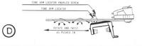
In Figure "D" the dust cover has been removed from the quartz chassis. Now remove the quartz chassis from the VTA base and place it, bottom side facing up, on a flat surface (use a cloth, etc., to protect top of chassis end moldings from marring/scratches ). Leave the chassis in this position while inserting the arm tube. Loosen the knurled screw on the tone arm locator and, holding the locator screw with one hand, slide the arm tube with cartridge attached into the locator until the rear of the headshell is approximately 1-1/2" (3.5 cm) from the center of the locator. Snug up the tone arm locator screw. With a felt-tipped pen, make a reference mark on the arm tube itself where it enters the front of the tone arm locator. Next attach the color coded phono lead wire to the appropriate terminals on your cartridge. Be sure to dress, or locate the cable as shown in Figure E, which is done to avoid having the leads touch the surface of the record.
FIG "E"
Install the counterweight cartridge weight(s), (2, 3, and 6 grams counter weights are supplied). Adjust the position of the counter-weight to apply the downward tracking force (see the next section) .
Note:
Because some cartridge combinations weigh more than 6 grams, it may be necessary to combine counterweights to get to the appropriate offset. This is normal, so use as many as necessary. In order to avoid swung weight resonances, join the two counterweights as closely as possible. If you are fortunate and obtain Souther-Suchy Veritas cartridge, it will have its own counterweight and special instructions included. The Veritas is an integrated M/C unit designed to be used in the Souther SLA are m/c unit; Please contact your dealer/distributor for an unforgettable audition.
Reinstall the quartz chassis assembly (with the stylus guard on the secured cartridge) and mount it into the bolted VTA base. Secure via screws.
STYLUS DOWNFORCE & CUEING
Use a calibrated digital downforce meter and follow the manufacturers recommended tracking weight for the cartridge. One caveat is make sure the digital meter has a weighing shelf that is only 2 mm above the platter surface.
TRACKING ALIGNMENT
The alignment process is iterative, and the steps are interactive. That is, changing one adjustment value will likely alter another. For example: when you change the height of the quartz track to adjust the VTA, you will also change (ever so slightly) the tangential alignment of the diamond with respect to the line on the linear line gauge. You must, therefore, change the position of the armtube in the locator which, depending on how much it is moved, will somewhat alter and impact the tracking force. Slightly annoying, but stick with it as with care and persistence, you will obtain maximum performance from your phono cartridge!
FOUR [4] SLA ALIGNMENT ACTIONS
1) ARMTUBE PARALLELISM
Place a record on the platter to establish that the arm-tube is parallel to the record surface when the cartridge is in the lowered (tracking) position. Adjust the SLA chassis assembly’s VTA setting (loosening the JAM nut and VTA red screw) so that the arm remains parallel to the surface of the record over the full lateral range of motion (use the cueing to lift and displace the cartridge arm-tube laterally) – you can achieve this in the following manner:
Sight in on the armtube, and raise or lower both the spindle locator and the VTA screw (whilst simultaneously loosening the jam-nut and the VTA screws) [using the same number of turns] and then use thumb pressure to push the molding (of the quartz rails) downward or upward to get the armtube perfectly parallel to the record surface. Double check that it maintains “parallelism” across the entire playback surface.
2) QUARTZ ROD [TRACKS TO PLATTER] PARALLELISM
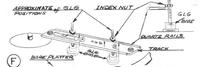
FIG "F"
Use the Great Little Guarge [GLG] to bring the quartz chassis assembly into perfect parallelism. To do this, remove the record and place the SLA chassis into play position, with the cartridge moved towards the center of the quartz track.
STEP A
Familiarize yourself with the SLA calibrated “units of measure”; each rotation per turn of the GLG “index nut” has the exact same vertical displacement as the “VTA screw” and also the “spindle locator”, which is 0.04 inch or forty thousandths of an inch for each full turn (or 1.00 mm per full turn).
Each full turn = .040” (1.00 mm)
Each 1/2 turn = 0.02” (0.50 mm)
Each 1/4 turn = 0.01” (0.25 mm)
Each 1/8 turn = 0.05” (0.12 mm)
STEP B
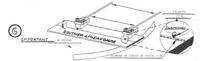
Place the GLG on the platter directly behind the rear quartz rail over to the left and just right of the level. Now (with the index nut slightly above the quartz rail) move the threaded shaft of the gauge towards you until it is against the quartz rail. With your index finger pushing down on on the GLG threaded shaft and spin the index nut until it just touches the top of the quartz rail.
STEP C
FIG "F1"
Lift the GLG up and out. Holding it by the base, unscrew the GLG index nut one-half turn EXACTLY. (Unscrew = turn counter clockwise). Now, place the GLG to the right side of the platter (way out towards the outside of the platter). Place the GLG in against the quartz rail with the threads touching the rails as in the previous step, near the level. If the track is close to being Parallel, the GLG threads should fit against the rail. (If not, open one-half turn more or, for a total of one turn.) Now, spin the “index nut” down carefully, noting the number of turns (or the partial number of turns) spun. Stop when “index nut” stops rotating as it touches the quartz rail.
STEP D
Keeping in mind that the “VTA screw” and the “spindle locator” move the same amount per turn as the index nut, and since you have noted the number of turns, rotate the VTA screw (clockwise) the same number of turns that the index nut moved to touch the quartz rail. This should have caused the track to move upward the distance it was down or out of parallel. Now, after couple of readjustments, you should be within a couple of thousandths of parallelism or “dead on.”
Note:
The GLG index nut will determine (by its position) how many thousandths (either up or down) from perfectly parallel you must move the spindle end up or down, or the VTA base end up or down. Repeated placement of the GLG at both ends of the track will indicate if the distances are equal. A caveat is that if the quartz track is not parallel, the VTA will change as the cartridge travels down the record: ergo (bad)!
Tip:
Many owners have misplaced their GLG’s, so a (slightly unwieldy) substitute for the Great Little Guarge [GLG] is to use two (2) depth measuring rulers.
3) LINEAR TRACKING
FIG "G"
Place a cleaned, dirt free and polished aluminium “linear line gauge” (supplied - part of the supplemental chassis packing) onto the platter spindle. You will be using the reference mark that you made earlier (the mark on the arm tube where it enters the tone arm locator). Cuing up the cartridge, move the carriage assembly with the horizontal cuing knob over the linear line gauge towards the inner part of the platter. Now lower the cartridge with the vertical cuing lever, and rotate the linear line gauge forward or backward, until the diamond is exactly in center of the linear line. Cue up the cartridge, and slide the carriage to the outer portion of the gauge, and lower the cartridge again. If, unfortunately, the diamond (which is very likely) does not drop onto the line again, do not panic! if it is forward of the line, pivot the chassis upward, loosen the knurled screw on the locator and slide the arm tube forward the same offset distance that the diamond was forward of the line previously. Use the felt tip pen mark (on the armtube) for a reference. Redo. If the diamond was “off” again, mark the armtube (using a felt pen) and slide the arm the same distance (forward or backward) , and lightly tighten knurled screw on the tonearm locator and recheck positioning with the gauge at couple of the line points; repeat these actions iteratively, until the diamond will drop into the linear line gauge radial line at all points. Recheck the tracking force.
Note:
It is useful when calibrating the radial line to use masking tape to secure (fix) the platter, so that it does move.
Note:
The placement of the diamond is extremely critical to the quality of the reproduced sound. We cannot emphasize this fact too strongly. Uniquely, your Souther may be set to within +/- 0.001” tolerances, the tightest in the industry (to date).
4) ADJUST AZIMUTH
FIG "H"
After the radial (linear) line tracking has been established, the next step is to adjust the Azimuth of the stylus. The jist of this technique is to use the rod assembly to determine if the cartridge mounting shelf is horizontal, and assumes stylus orientation is at right angles to the cartridge body.
Note:
Phono cartridge azimuth adjustment is the process of aligning the cartridge so that the stylus tip - actually the stylus tip sides) will seat correctly within the cut record groove walls at the correct angle. This adjustment is important for optimal channel separation.
With the cartridge cued up, center the azimuth rod (supplied) into the groove, in the top front of the headshell. Lower the cartridge until the diamond is almost on the platter and, using your eye, check to determine if the distance from both ends of the rod are an equal distance from the platter. By using the GLG, you can set the azimuth within a thousandth of an inch! Rotate the cartridge and recheck with the azimuth rod until you once this has been established, are satisfied that a = b. Tighten the tone arm locator set screw firmly, using thumb and index finger. If you are using a solid arm tube you may use the hex key wrench (supplied) to further tighten the tone arm locator screw an additional one-quarter turn (but not more than 1/4 turn!). If the bubble on your track is not level, you must adjust your turntable feet, or shim the feet until the bubble is exactly centered! Do not –repeat– do not try to achieve bubble centering with either the “spindle locator” or the VTA screw. This is because to move either one without the other will disturb the “track to platter” parallelism!
Note:
After the above mechanical steps, electrically check Azimuth with a test record designed to measure crosstalk.
OPERATIONAL MODE
To return the cartridge to its “start position”, after it has be lifted by the magnet (or at any time during play) first cue-up the cartridge by using the vertical cue lever. The (imporantant) use the lateral cuing knob on the carriage to slide the whole arm and cartridge assembly towards the hinged base, which is the right side of the chassis, and the beginning of the record tracks.
Do not be concerned with the force needed to pull the cartridge carriage away from the magnet.
An alternate method of returning the carriage and tone arm (once off the magnet) is to slowly lift the quartz chassis up from the spindle, slowly
Warning:
Do not lift the quartz chassis quickly, as the cartridge carriage assembly will slide down at “9.8 meters per second squared (m/s²)” and impact the side-stop, which risks all of the above calibration steps.
NON-CRITICAL ADJUSTMENTS
MAGNETIC LIFT
CFP: I do not use this – removed.
CUING HEIGHT
Cuing Height may also be readjusted: This adjustment screw is located under the track, on the hinged base end of the chassis. It is a slotted screw and locknut. The cuing height was adjusted at the factory prior to shipment, and the only time it need be changed is when you find the vertical cuing lever in full up position causes the horizontal cuing action to be not as smooth as when the cuing lever is lowered slightly. When this condition exists, you will also note that as you reach maximum upward throw of the vertical cuing lever, the front of the carriage will raise slightly. This causes a binding condition of the carriage which may be removed by screwing the aforementioned adjustment screw. This to a point where the carriage front barely cuing of the carriage is as smooth at full upward throw as when nearly fully up.
Tip:
If, after repeatedly “cueing-up” your cartridge, possibly using too much force, you may notice that the cueing lever gradually goes higher and higher. This is due to the cue lever friction pivot. No worries - this condition is easily corrected by (forcefully) rotating the lever down to its “stops”, when the cartridge carriage assembly positioned at the far right and down position. In the future, change the habit and use less lift force (lift it gently) and you will not have this issue.
FINAL SET-UP [VTA/SRA]
This step is done by listening and is vitally important in order to extract the optimum sound from your cartridge. Upon completing set up of your Souther, as described previously, the careful owner is left with the task of adjusting the vertical tracking angle (VTA). VTA accuracy can be best attained by listening. Select any well recorded disc, in good condition, with a vocal soloist.
Tip:
Some suggested LP Records to use when determining VTA/SRA (voice focused):
Mobile Fidelity pressing of Gordon Lightfoot’s “Sundown”
Opus 3 Record’s “River”
Carol Kidd All My Tomorrows (Aloi, 1985) “Don’t worry about me”
Harry Belafonte Belafonte at Carnegie Hall Live (RCA, 1959) ”Sylvie"
Place the arm tube out of parallel with the record by several degrees. This is accomplished by loosening the spindle locator jam nut and rotating the spindle locator several complete turns [note your turns], either up or down, and locking the jam nut. Next, loosen the same hinge base of red VTA lock screws and rotate the exact same number of turns as you rotated the spindle locator. Then retighten the lock screws.
Then examine the voice in the same way as one would examine an image while focusing a camera. If you move VTA too high (or too low) the voice will become flat, dimensionless and adorned with edge. As the “sweet spot" is approached, the voice will gain body, depth and resonance---in short, it will sound more human.
Treble and bass will differ in the manner they are affected by VTA , but the voice test is a clear, repeatable test that is very telling. Please remember: Any appreciable change in the VTA will require that the Quartz rod assembly tangency be re-established. Be patient, thorough and persistent. The results will pay you back in performance. Always be certain that both the platter and track are parallel and level.
MISCELLANEOUS
Tip:
Polish your platter center spindle top (the tip) to be “ultra smooth” [ mirror bright – 14 micron diamond polishing sandpaper did the trick for my Kuzma Stabi S] – experiment with an ultra-light coating of petroleum gel on the tip and in the spindle locator (Teflon) recess. A later modification makes this unnecessary, but if you have an earlier model, it helps.
No one on the planet seems to know how to properly set up a Souther-style linear tonearm. So - without further delay - here are some must-do’s/must-remember. Anyone please feel free to ask anything or debate what I’ve written. Only a few of the below applies to linear arms in general. Maybe someday I’ll get truly nuts and grab a Walker table or maybe just an Airtangent arm. Who knows what occulted disasters lurk in the realm of the air-bearing linear tonearm… Anyway:
Light cartridge, pref. < 7 grams
Counterweights far as possible from fulcrum- yes, the opposite of a classic single-pivot arm; cart. weigth is a variable of course. Having < 20Hz vertical res. freq more important than lowest possible moment of inertia.
Leveling- forget that “set for slight downward-angle” (toward spindle) crap. Level the sucker. Downward angle is only relevant when considering that perfect level is not possible; error (read tiny error) should be downward toward the spindle.
Don’t take the dust cover off the arm chassis (certain models only). Screwing it back on could bend the arm. Pressure is oh-so-easy to apply unevenly. Only experts should attempt this.
Never never never use isopropyl or any other solvent to clean the quartz tracks- I’ve had glue holding the track to the chassis actually fail and the track hang off the chassis. Blow with “duster” style air cans (no moisture). I’ve resorted to cleaning the tracks ever-so-delicately by hand with a dust-free cloth.
Keep those wheels clean- not unlike a friggin’ PC mouse :)
Funny to say this, but don’t lift the chassis without first cueing the tonearm full right. I’ve seen people just gleefully watching the entire tonearm/cart. assembly slide down the rail and _WHACK_!, right into the stop, over and over again. Then, “Hey, why does my azimuth adjustment keep going off?”
Making different VTA/SRA adjustments: Hahahah. Good luck.
Hierarchy of parameter interaction/basic setup elements: First, arm chassis is lined up, counterweights and arm set at best estimate (cart. attached). Set VTA/SRA 1st with that gawd-awful-better-just-want-one-VTA-setting screw arrangement. Then, set linearity of tonearm proper in relation to spindle. Azimuth adjustments are best done next. Then, adjust tracking force by moving weight(s). Failure to set up in that order will result in alteration of parameter(s) that the user previously set.
VTF- use slightly more, ie, w/ range of 1.8 to 2.2g, use 2.1-2.2g.
Phono IC’s- get integrated phono IC outs from the tonearm chassis. Do not get the default RCA post option; the RCA’s on the cables you use will spin and be stressed when moving the tonearm chassis up and down with all but the flimsiest of phono interconnects. RCA blocks on tonearm chassis get scratched, damaged, and worn. Worse- you get RCA phono IC’s with those screw-snug connectors, and gradually rip the RCA posts loose on the tonearm chassis with the repeated up/down lifting of the chassis over time.
Hope the few of you out there still using Souther design arms have enjoyed this information. Feedback encouraged. -M meister, Sep 7, 2003#1